TOP
TOP

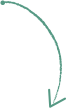
Link function is supported for convenient operation when moving positions using multiple elements such as products, cores, and chillers. By linking two or more elements to each other, when one element is moved, the linked element is automatically moved to the same position to prevent errors that may occur during design.
Quickly edit your design
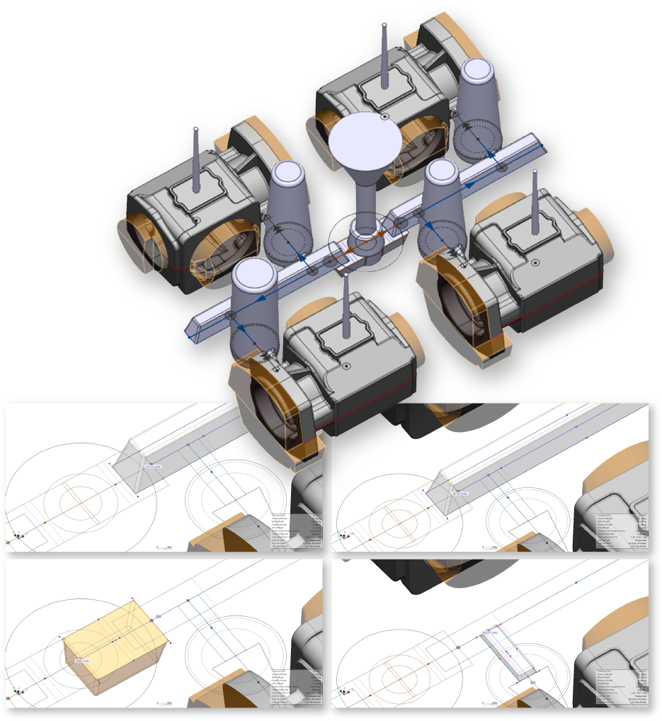
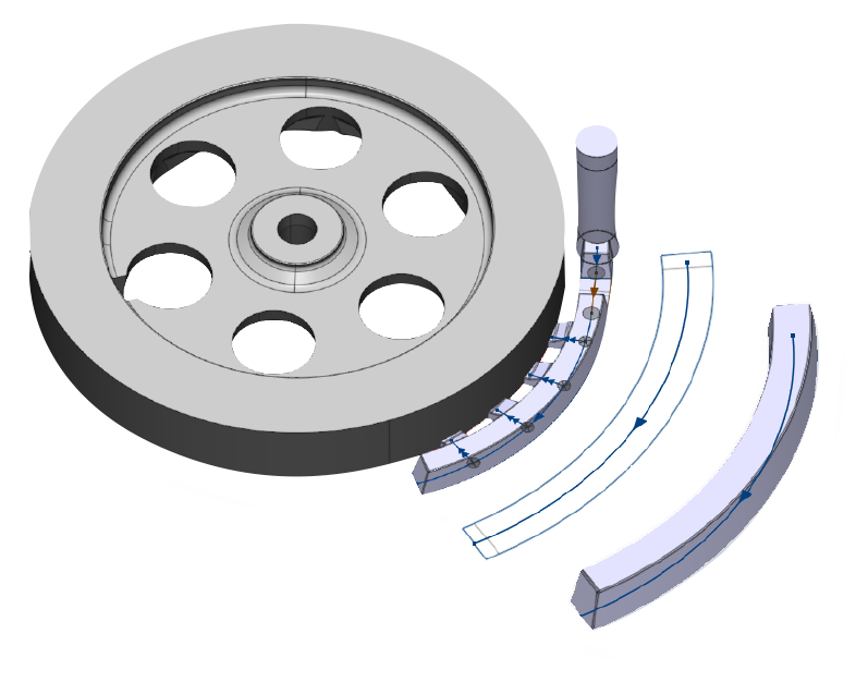
It is classified as ‘Pouring Path’ within AnyDESIGN, and it is divided into three steps of ‘Pouring Basin/ Sprue/ Sprue Base’ to adjust the value of each element.
It is possible to implement everything from the general runner shape to the curved runner shape, and it is also possible to implement multi-stage shapes and select the cope/drag position.
Quickly edit your design
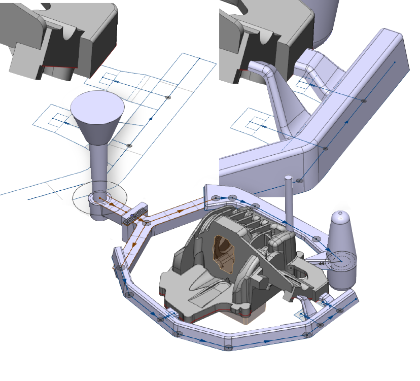
If there is a level difference between the product and the connection point at the starting point of the straight flat ingate and the ingate branched from the runner, it is classified as a 3D ingate in use.

Quickly edit your design
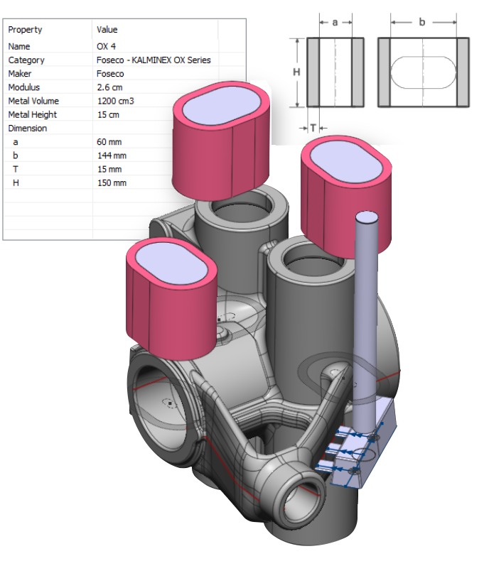
‘Side Riser’ and ‘Top Riser’ are separated, and the riser neck creation function is also supported.
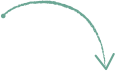
Design at AnyDESIGN basically expresses the entity-based elements freely on a 2D plane and then proceeds with the implementation of 3D shapes. In addition, the 3D shape preview function is supported to check the numerical values entered when creating each element.

Quickly edit your design